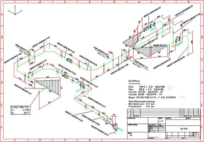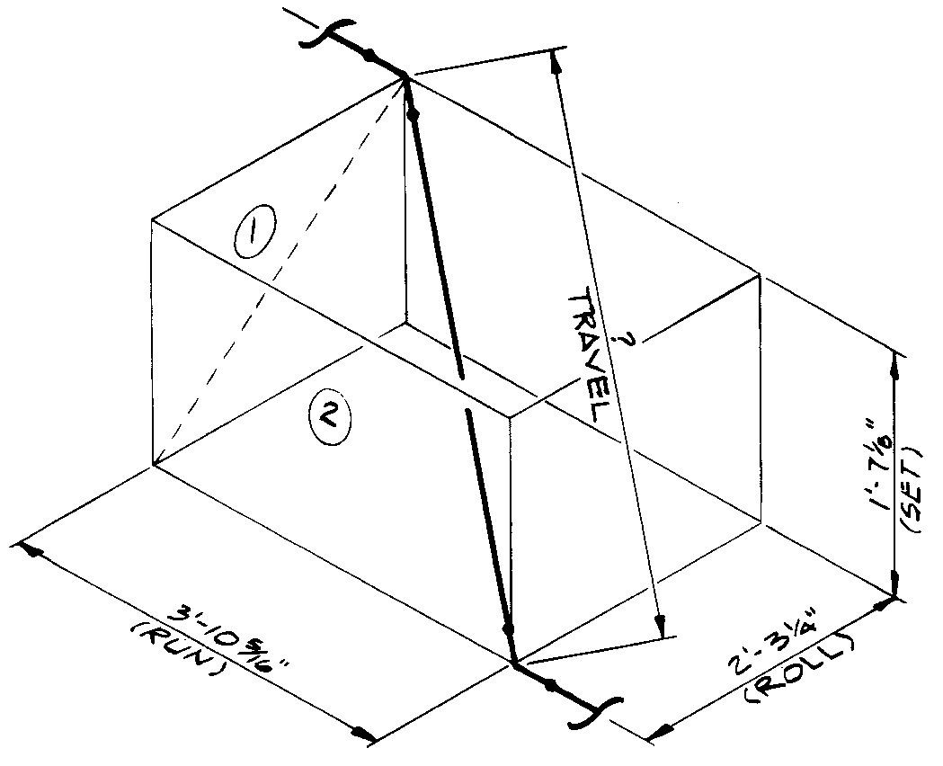
Typical diagrams are of the water-supply system and the sanitary stack. Generally, the engineer draws a plumbing plan and connection diagrams. Some projects require piping for equipment as well. These plans show the engineer the location of plumbing fixtures such as toilets, sinks, and water heaters in the design. They are based on plans provided by the interior designer or architect. They must comply with the National Plumbing Code and with national, provincial, and local codes.Įngineers produce their own drawings. All related plumbing lines drains, connections, and vents must be installed according to the approved drawings.Ī mechanical-engineering company produces the drawings. They are also part of the package for pricing the project for the client.

In most cases, they are submitted with the construction drawings for a building-permit application. Plumbing drawings are typically part of the construction-drawing set. Figure 6.19 shows a schematic isometric of a two-bath plumbing system and the various connections and outlets needed. Vents allow built-up sewage gases to escape and pressure in the system to equalize. All drainage pipes must be connected to vents. A waste stack carries the other waste from a sink, washing machine, or dishwasher. This seal prevents gases from the sewage system entering the building.įrom the trap sewage travels through drainage pipes in branch lines to a vertical stack. The trap catches and holds a small quantity of water to provide a seal. Some traps are part of the design of the fixture and are not visible, as in a toilet or double sink. A trap is the u-shaped pipe found below a sink. The first component connected to a fixture is a trap.

Plumbing drawings are usually numbered beginning with “P,” as in P-1, P-2, etc. A plumbing floor plan will typically show the location and type of plumbing fixtures, as well as the route pipes will be run (overhead or through walls) for potable water, drainage, waste, and vents.

Drainage works by gravity: Drain pipes must slope downward. Water is supplied under pressure through pipes to plumbing fixtures. Plumbing systems involve two major components, water supply and drainage. Plumbing drawings provide all pertinent information on the design of the plumbing system for a project, including line sizes and location, fixture location, isolation valves, storage-tank capacities, hot- water-heater capacities and locations, and drain locations and routing.


 0 kommentar(er)
